One August morning I was driving my daughter to work, and I noticed a knocking coming from under the hood. Uh oh. I get her there, and take a look at the oil level. Hmmmm. Two quarts down out of eight, not to bad. But the knocking is annoying. Last time I heard a sound like this, is was because the cam gear retaining clip had shattered and the gear was wandering around on the end of the cam. The sound is the same, and doing the usual tests for rod bearing slop eliminate that. How do you test for rod bearing? With engine running, pull the plug wires one by one. If you get to a cylinder that has a bad rod bearing, the intensity of the knock will quiet down considerably as the piston is no longer firing. Also, when revving the engine, if there is a bad rod bearing the knock will get louder. In this case, as was the case before, the only think that changed with revving was the frequency of the knock.
So, I resigned myself to have to go in there again. Much of the procedure is on the cam gear replacement page, but I will summarize again here:
* First drain the coolant. It is very common for the drain petcock on the lower corner of the radiator to become plugged, so the quickest way to drain is simply pull the lower hose off the bottom of the radiator.
* Next, drop the bib. There are 8 bolts that hold it onto the fenders and aprons. You don't have to completely remove the bolts, just loosen them, as the mating sheet metal is slotted. Unplug the headlight connectors. Put rags on the tow hooks, as that is exactly where the headlights will rest when the bib is pivoted downward on the hinge.
* Remove the top radiator hose, then remove the six bolts that hold the radiator to the radiator frame. My petcock had to be removed to clear the hole that it sits in. Then pull the radiator out. After that, remove the two bolts at the bottom of the radiator frame and pull the frame out. Loosen the alternator and remove the belt.
* The next step is to remove the "big ol' nut" from the crank pulley. First bend the locking tabs back. Then put the socket (size is 46mm or 1-13/16") on the nut, then lay the breaker bar on the frame on the driver's side. Then turn the key and crank the engine just a little. That will loosen the nut and it will come right off.
* After getting the big ol' nut and locking washer off, use a harmonic balancer puller to pull the crank pulley off the front of the crankshaft. Remove the splash shield from under the pulley first so the pulley will clear enough to slide off.
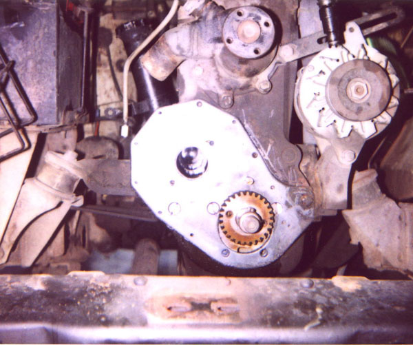
* Next, the timing gear cover can be removed. Take care to notice where the bolts go in which holes, as they are different sizes. Pull the cover.
When I removed the timing gear cover, I discovered that the cam gear retaining clip was still in place from when I had replaced it the year before, so that couldn't be the cause of the knocking. I figured since I had already gone to the trouble to get in that far, I may as well install the new cam gear that I had gotten previously, to replace the old one which had a chip in one of it's teeth.
I removed the clip and pulled the gear off, then put the new gear in. Something wasn't right though, I expected the new gear to press on, but I couldn't get it to stay in one spot. I expected the old gear to be loose from when the clip had broken previously, but the thrust clearance was excessive, it was .040" or more, compared to spec. of .006" to .012" max. Clearly something was wrong, and a couple phone calls to some buddies more knowledgable in these matters than I, revealed that the only likely cause was that the end of my cam had worn so much that the new gear could not be pressed on to the proper thrust clearance. So I resigned myself to having to buy a new cam. I ordered the new cam in, then set about removing the old one. Considerably more disassembly was going to be required.
In order to slide the cam out, the lifters would have to be pulled up off the cam, and to do that I had to:
* Remove the valve cover.
* Remove the rocker arm assembly, and oiler from the rocker arm assembly.
* Pull the push rods out. Keep them in exact order for reassembly!!!
* Remove the side cover. In order to do this the distributor must be removed too, so line the engine up to top dead center, compression stroke. The rotor will point toward the spark plug hole for #4. When you slide the distributor out, it will rotate clockwise as it's teeth disengage with the teeth of the gear on the cam that drives it. The fuel pump was also removed as it is in the way of removing the side cover.
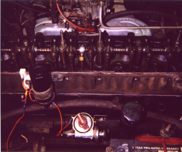
The photo below shows the side of the engine at this point of disassembly.
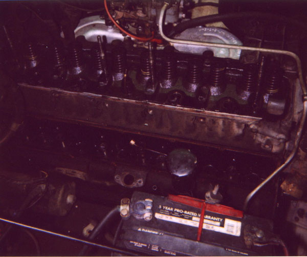
* Remove the lifters, again, keeping them in order. Some of them had varnish deposits on them and they couldn't be readily removed, but they could be pulled up enough to clear the cam lobes.
* At this point, I realized that the bib, even flipped down was in the way, so I had to remove the bib from the hinge at the bottom. Then I discovered that even the hinge was in the way, so I had to remove the hinge from the frame crossmember. To gain more clearance, I also removed the fan from the water pump pulley.
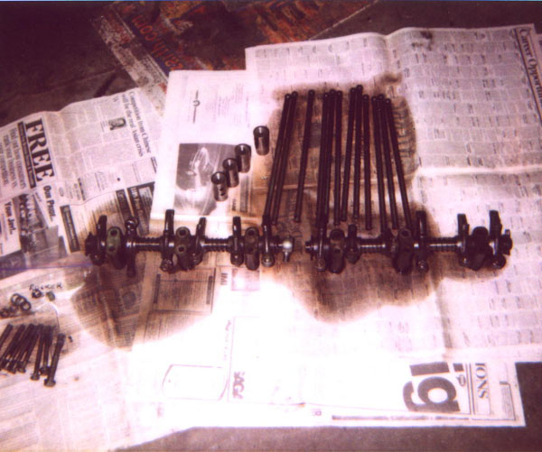
Now the cam could be slid out. The photo below shows the cam, with timing gear resting against the frame horn.
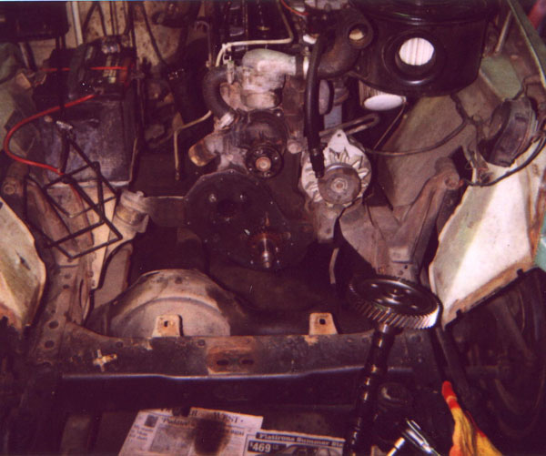
The photo below is kind of a neat view looking staright down the the hole where the cam goes.
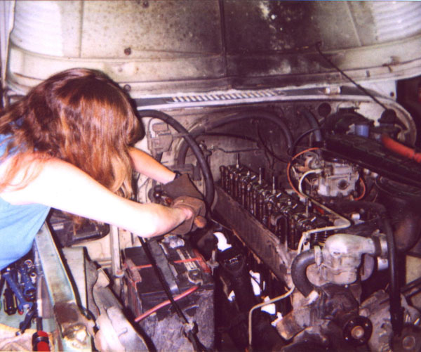
The most important thing to prevent leaks is proper surface preparation. The side cover gasket is probably one of the most difficult gaskets to completely remove. Most of it will be stuck to the block, although some of it will come off with the side cover. Wire wheel the gasket mating surface of the side cover.
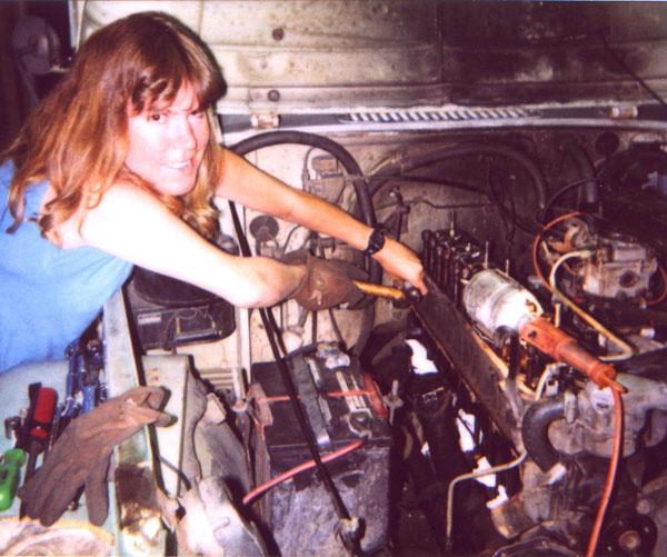
The get the gasket pieces off the block, I used a gasket scraper, a screwdriver, a putty knife, a razor scraper and in some cases a hammer to help drive the various scrapers. Plug up all the holes and passages with paper towels or pieces of clean rags to prevent anything from falling down into the engine. The photos below show my wife Ann helping scrape gasket.
After as much scraping has been done as possible, there will still be lots of pieces still stuck to the block, and scraping reaches the point of diminishing returns. At this point, a wire wheel will get all the rest of that off very well, and leave a smooth shiny surface for the new gasket to make a leak proof seal.
To get the side cover gasket to align properly, put a thin bead of sealant such as blue permatex, along where the gasket goes on the side cover. Then lay the new gasket on it and hold in place by inserting the four corner bolts. Let it set up an hour or two. This way, the gasket will stay perfectly aligned when the side cover is lifted vertically into place.
The photo below shows the proper alignment of the distributor when it is reinstalled. Bear in mind that you need to point the rotor at #3 when you first slide it in. It will rotate counterclockwise as it's teeth engage with the teeth on the cam. Make absolutely sure that the end of the distributor shaft is fully engaged with the slot on the oil pump. You can reach in there with a long screwdriver and turn the pump to get it lined up just right to engage with the end of the distributor shaft when the shaft is slid in.
Reassembly is pretty much the reverse of disassembly, as they say in the manuals. A couple of tips:
* Use a new seal and new gasket on the timing cover. You'll be glad you did. Use the same scrape and wirewheel method to prep the gasket sealing surfaces of the timing gear cover and block. Smear a thin film of grease all over the front crank seal before installing it into the timing gear cover, this helps a lot. Be very careful not to damage the seal when pressing it in.
* Be very careful not to over torque the little 10mm head bolts that hold the side and timing covers on, I use a 1/4" drive ratchet for this. Remember that the timing gear cover bolts are different sizes, make sure to put them back in exactly the same order. You must cover the threads of the two bottom ones with sealant, I use blue permatex.
* You will need to readjust the valves before putting the valve cover back on. .008" for intake, .014" for exhaust. Even though this is a cold adjustment it will get them nominal and the engine should run fine. After a couple warm-up/cool-down cycles, go back in there and do a final hot adjustment.
* Tighten the distributor clamp to the block, but leave the adjustment clamp loose. You will need to reset the timing when you first start it up. My engine started right up when I was done reassembling everything, good thing I paid strict attention to details.
EPILOG:
This didn't fix my knock, even though I now had a good tight press fit on cam timing gear on the cam, and the cam thrust clearance was now within specifications. Subsequent diagnosis some months later was that I had a worn wrist pin.
Of course this didn't help my low oil pressure, which is caused by worn main bearings and rod bearings, or oil consumption. The cruiser still ran well, but I was afraid to take it wheeling for fear of blowing the engine far from help. Some places you REALLY don't want to have to be strapped out from.
I finally decided to replace the engine with a used F of the same vintage so that I would have a chance to completely rebuild this one before I put a piston through the block and rendered it unrebuildable.