The Land Cruiser Restoration Project
Resto Home Page
Page 1 2
3 4 5
6 7 8
9 10 11
12 13 14
15 16 17
18 19 20 21
22 23 24
25 26 27
28 29 30
31 32 33
Next up is a fairly ambitious part of the project, but something that most cruiser owners have to deal with sooner or later. I had originally decided to leave the brakes, differentials, axles and knuckles until later in the project, because it doesn't matter a whole lot whether the body's on or not. But still, everything's easier with the body off, and I had gotten a knuckle rebuild kit and new tie rod ends from fellow Rising Sun member Jim Sanville, who is also a TLCA Associate business with his Canon City 4x4 shop. Part of this whole phase will involve swapping the front diff into the rear and the rear into the front, and of course you must have the axles out to do that. The rationale for the diff swap was that the front, with very little wear should go in the back where it sees most of the miles. In the meantime, the rear, which would have a lot more miles on it, will go into the front where it will only see any wear when the front drive is engaged. Last, I will be installing a Lock Right into the rear toward the end of this phase.
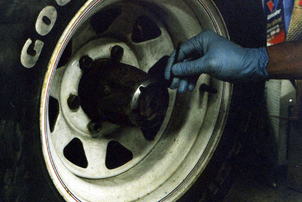
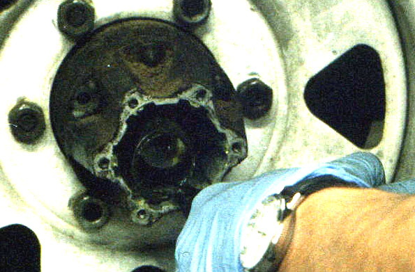
Below, the first step is removing the cap or "dial" from the Warn locking hubs. These use an allen wrench rather than the 10mm hex head that the Aisin locking hubs use. Next the cap comes off.
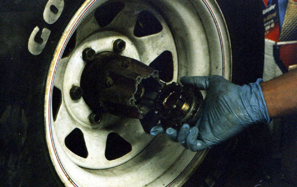
Then the 12mm bolts that hold the locking hub to the hub itself are removed. Again, this is a Warn locking hub, which means that there are no cone washers. It's tough to see, but the next photo shows the circlip being removed from the outer birfield stub. With the right kind of pliers, it's quick and easy. With conventional "snap-ring" pliers its pretty difficult, and prying it with a screwdriver is actually easier. Now the locking hub can be removed. Whoever was in here last didn't bother to get OEM paper gaskets for the hub, there is red gasket goo everywhere!
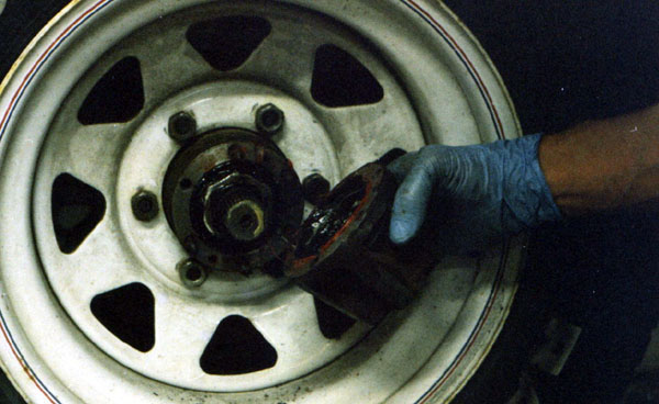
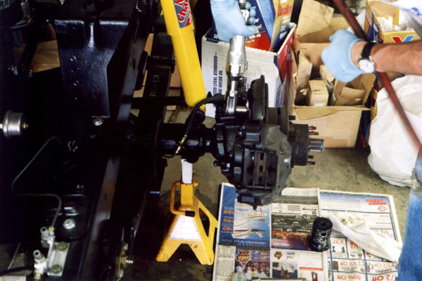
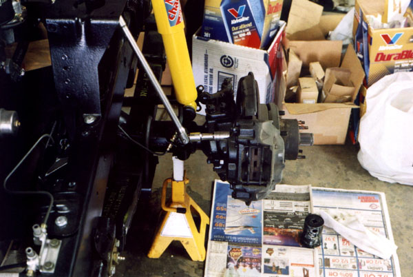
Next I put the cruiser up on jackstands and take off the wheels. There is a view of the assembly on the passenger side before going farther. The next two photos shows the driver's side, already stripped down to the axle housing with the knuckle completely removed. I concentrated on making a step-by-step tutorial on the passenger side, but there are a few driver's side shots here and there.
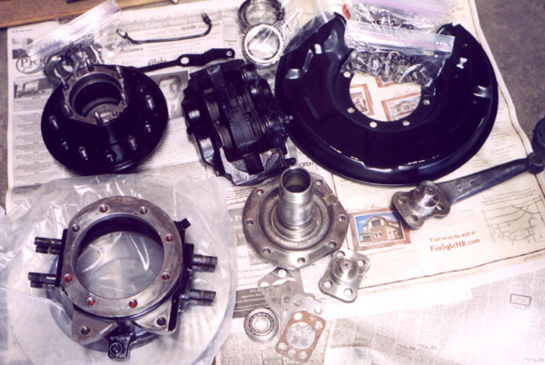
The photo below shows all the parts after they have been cleaned in the parts sink, wirewheeled and painted. Jim's rebuild kit included a set of knuckle shims, which turned out to be critical. Whoever was in here before (driver's side) had replaced the tapered roller bearing on the top of the knuckle with ball bearings! Plus, there were no shims at all. I would have to start from scratch to get the proper axle alignment and preload.
People have commented to me that it must take a lot of extra time to take all these photos instead of just going about the work. It does. And what takes even more time, is cleaning all these parts up, wirewheeling them, masking, and painting multiple coats on all sides. If you were just going to rebuild and do a quick cleaning in the parts sink it would have taken far less time. As it was, this whole front end job took several weekends. And here it is, Labor Day weekend 2003, and I am waiting for paint to dry on the rear brake backing plates as I write this page. Hopefully I will get the rear brakes and differential done this weekend.
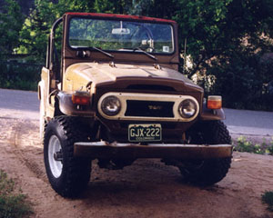
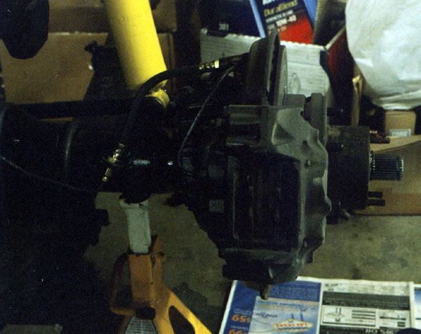
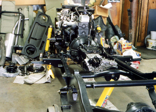
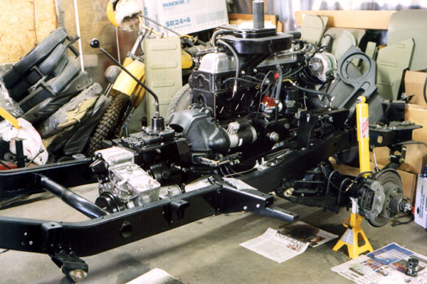
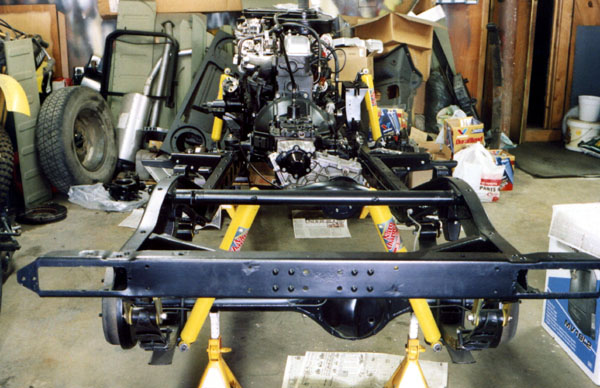
For the next five shots, I had the camera out and decided to get some photos of the whole thing up to this point from various angles. Slowly but surely it's coming along. As I have mentioned before, what started out as a body resto has evolved into a complete rebuild, putting it back to as new as the day it rolled down the assembly line at the Araco plant in Japan where it was built in April of 1976.
Now, back to the right side. The locking hub and wheel are off. Next is removal of the brake line brackets. There are 3 bolts on the top for the brake line bracket, one of which is shared with the backing plate reinforcement bracket. The brake backing plate reinforcement bracket goes along the cutout in the backing plate on the caliper side, and provides stiffness for the backing plate.
Next, the caliper can be unbolted. Often, the caliper is simply moved out of the way. When this is done, it is usually difficult to get the backing plate over the spindle, as the brake line doesn't leave much service length. If this happens to you, you can slightly loosen one of the flare fittings on the hardline to allow it to pivot a little more. If you remove the entire brake line as I did, then it comes off easy. The downside is that you have to bleed the brakes after the brake lines are reinstalled.
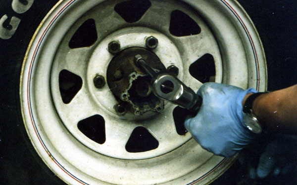
The locking nut is removed.
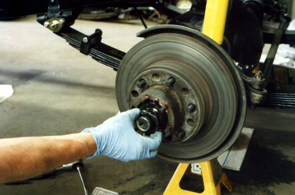
Then the star locking washer comes out. These can be reused in a pinch, but it is normally better to use new ones. They are inexpensive.
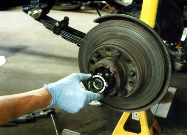
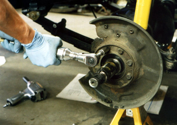
The next step, not shown, is removing the adjusting nut. Now the entire hub can be withdrawn over the spindle. The rotor is bolted to the back of the hub; it will be replaced later. I left the bearing retainer and outer bearing on, they are easier to remove by simply pulling the hub off.
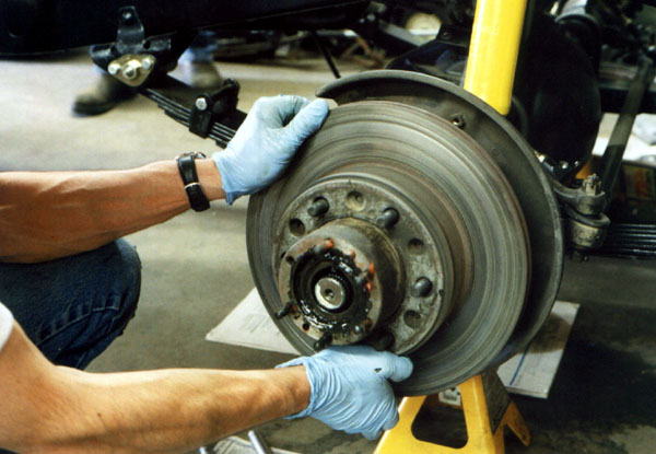
Now the brake rotor is unbolted from the hub.
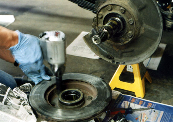
Next, I use my seal puller to pull the inner grease seal from the hub.
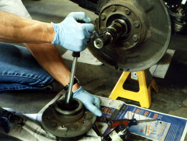
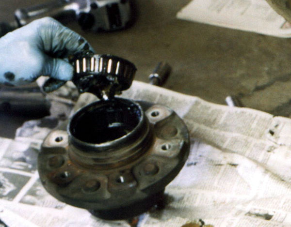
With the seal out of the way, the inner bearing can be removed. These bearings were cleaned, blown dry with compressed air, then given a thorough visual inspection. The inspection showed that they were in excellent shape and could be reused.
Now the backing plate outer grease seal is removed. Often, these can be reused, but my rebuild kit included new ones. I cleaned these up anyway in case I need an emergency spare at some point in the future.
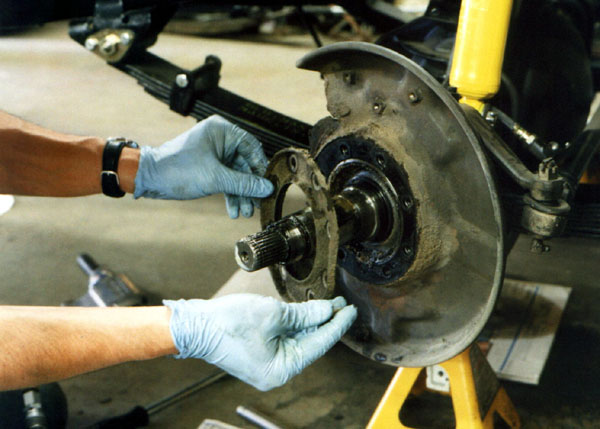
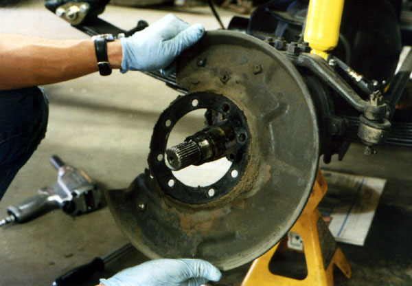
Next the brake backing plate can be removed over the spindle.
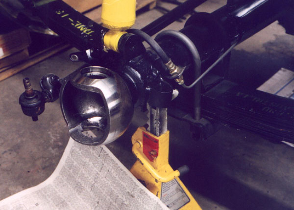
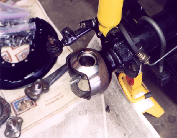
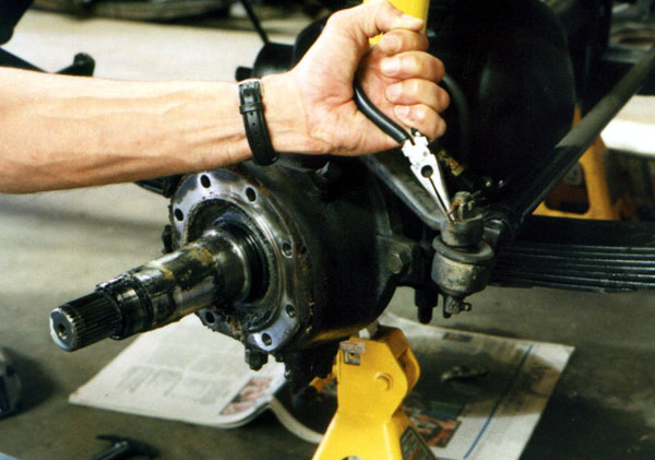
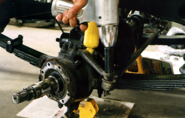
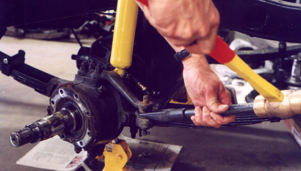
In order to replace the knuckle bearings, the steering arm must be removed. In order to do that properly, the tie rod end must be removed. First the cotter pin is removed, then the nut is removed, and last the tie rod end is separated from the steering arm with a pickle fork. The tie rod ends will all be replaced with new later in the project, so I'm not worried about messing up the rubber boot. In fact, the boots have been pretty worn out for a lot of years.
The next three pages will show the rest of the knuckle rebuild, and some differential and rear axle stuff. As I said, I am swapping differentials from front to rear and rear to front while I have the axles out.
Page 1 2
3 4 5
6 7 8
9 10 11
12 13 14
15 16 17
18 19 20 21
22 23 24
25 26 27
28 29 30
31 32 33
home what's new cruiser links trail reports cruiser sightings land cruiser tribute tech tips photos maps band links misc links profile email