Page 1
2 3 4
5 6 7
8 9 10
11 12 13
14 15 16
17 18 19
20 21 22
23 24 25
26 27 28
29 30 31 32
33
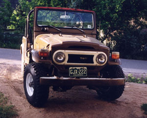
The Land
Cruiser Restoration Project
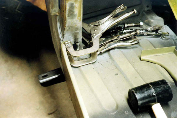
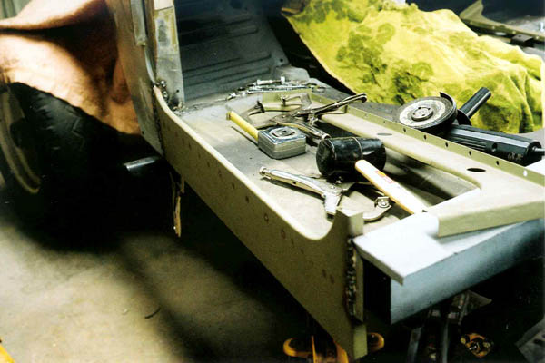
To weld the outer driver's side rocker panel to the a-pillar, it's clamped firmly with c-clamp vice grips.
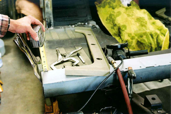
The rear of the outer rocker panel is measured carefully to make sure it's even with the already-welded passenger side. Obviously, after it's welded, there's a lot less opportunity to change it!
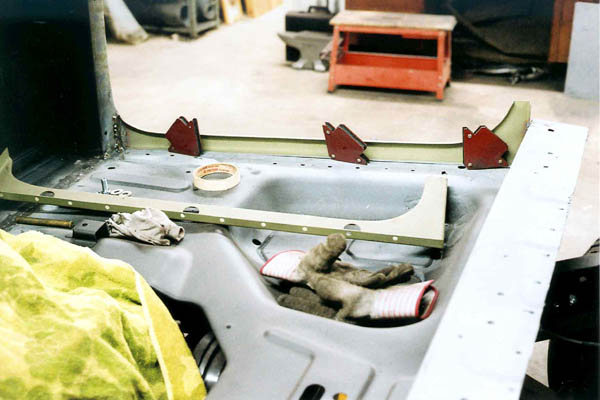
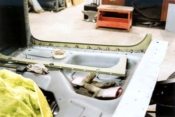
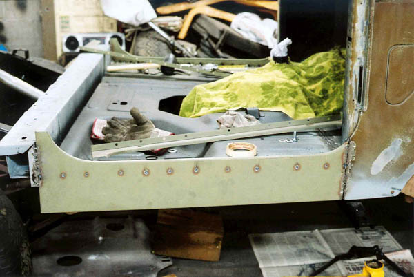
As I had mentioned previously, there was about a 1/8" gap between the outside edges of the floorpan and the inside of the outer rocker panels. I made up some reinforcements from some 1/8" thick 1/2 x 1/2 angle iron, and used it to not only shim the gap, but reinforce the floorpan. In the photo below, you can see where it is welded in to the inside of the rocker panel and the edge of the floorboard. Prior to taking this photo, I had already welded up the front and rear of the rocker panel.
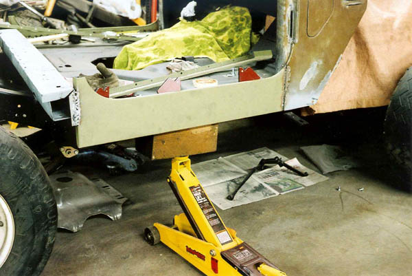
This is what it looks like from the outside.
I hade to shim/reinforce both sides. Not shown on the driver's side, but shown here, is how I leveled the floorpan by supporting it from underneath with a chunk of landscaping timber on a floor jack. This got it lined up level and not sagging, as it would have been if I hadn't supported it.
On the inside seam. I used welding magnets to help hold the pieces together prior to welding. These magnets are wonderful!
This is what the passenger side looked like after I welded in the angle iron shim/support.
Outside view of the passenger side outer rocker panel after the shim is welded in.
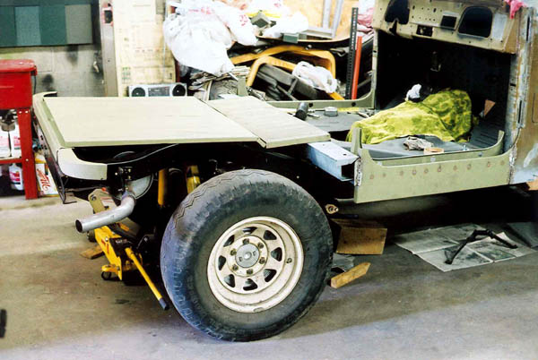
Next, I laid out the CCOT mid bed, rear bed and rear channel to see where they would go, how they might line up and what it would look like. Even though it's been years since I bought them, a few phone calls and emails with CCOT really help clear up some confusion I had about how they went in and in what order.
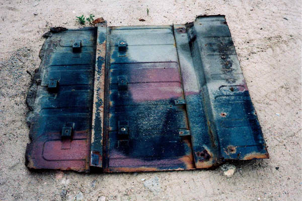
I suddenly realized that I was going to be needing a bunch of parts off my old rusty bed. The rear cross channel, the six heat shield mounts and two other mounts would need to be cut off, sand blasted, painted and welded to the new rear bed. I had a new CCOT front cross channel that goes under the rear bed and the mid bed, so at least I wouldn't have to prep that. I was sure glad I kept all those old parts. Even the ones that wouldn't need to be re-used are still handy for reference, to figure out how the parts are supposed to go together!
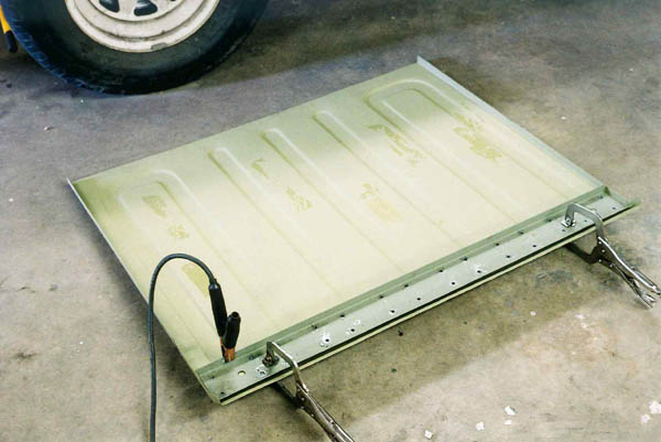
The photo below shows the new CCOT front rear bed channel laid across the new CCOT rear bed. The gap across the edge is where the angles didn't line up right. Between vice gips, my sheet metal brake and a few well-positioned blows with the rubber mallet quickly got the angle corrected.
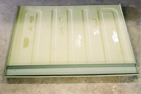
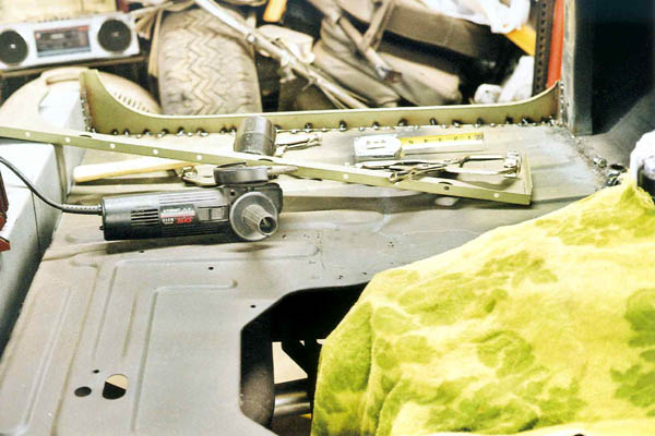
In order to simulate the factory resistance spot welds, I drilled holes in the cross channel. I also ground through the primer on the CCOT rear bed where the holes were to get good electrical contact where the welds MIG would go.
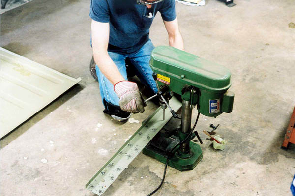
I also ground through the primer paint for a good ground for the welder. Here it is all lined up, clamped and ready to weld.
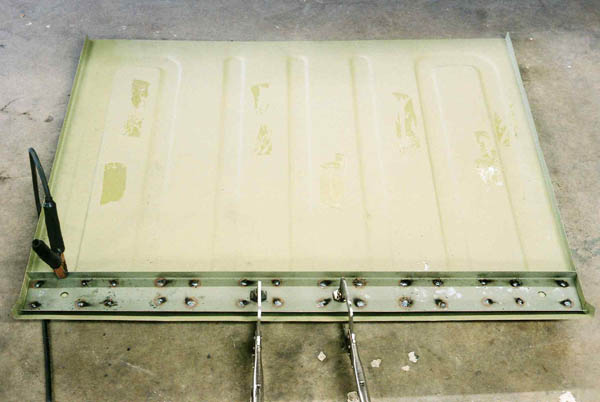
The welds in each hole replicate the factory resistance spot welds.
Page 1 2
3 4 5
6 7 8
9 10 11
12 13 14
15 16 17
18 19 20
21 22 23
24 25 26
27 28 29 30
31 32
33
home what's
new cruiser links
trail reports cruiser
sightings land cruiser tribute tech
tips photos maps
band links misc links
profile email